
NEXEM Miniature Power Relays | NAC Semi
Product families
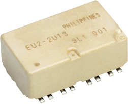
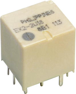
View all 10 family images
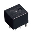
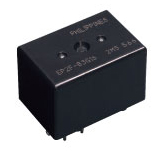
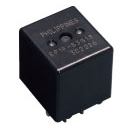
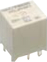
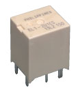
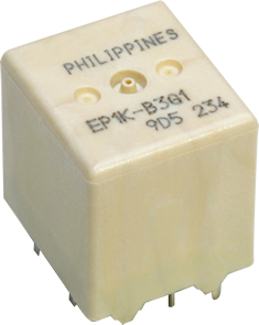
Images represent product families; appearance may vary by option.
Compare products
Search across the table or filter individual specifications. Scroll sideways for additional columns.
| Web Images | Datasheet | |||||||||
|---|---|---|---|---|---|---|---|---|---|---|
EU2-2U1Product notesNotes: Coil resistance and power apply to each relay unit. Carrying-current PCB: FR-4 1.6 mm; copper 105 um thick, 10 mm wide, 40 mm long. Switching Current Conditions: Maximum per datasheet | View image ↗ | EU2 | 12 | Non-latch | 1 Form C x 2 (Separate) | 30 | 16 | 960 | Surface-mount | PDF ↗ |
EU2-2U1SProduct notesNotes: Coil resistance and power apply to each relay unit. Carrying-current PCB: FR-4 1.6 mm; copper 105 um thick, 10 mm wide, 40 mm long. Expanded only using explicit enclosure/packing or L/N choices in the numbering diagram. Switching Current Conditions: Maximum per datasheet | View image ↗ | EU2 | 12 | Non-latch | 1 Form C x 2 (Separate) | 30 | 16 | 960 | Surface-mount | PDF ↗ |
EU2-2U1-TProduct notesNotes: Coil resistance and power apply to each relay unit. Carrying-current PCB: FR-4 1.6 mm; copper 105 um thick, 10 mm wide, 40 mm long. Expanded only using explicit enclosure/packing or L/N choices in the numbering diagram. Switching Current Conditions: Maximum per datasheet | View image ↗ | EU2 | 12 | Non-latch | 1 Form C x 2 (Separate) | 30 | 16 | 960 | Surface-mount | PDF ↗ |
EU2-2U1S-TProduct notesNotes: Coil resistance and power apply to each relay unit. Carrying-current PCB: FR-4 1.6 mm; copper 105 um thick, 10 mm wide, 40 mm long. Expanded only using explicit enclosure/packing or L/N choices in the numbering diagram. Switching Current Conditions: Maximum per datasheet | View image ↗ | EU2 | 12 | Non-latch | 1 Form C x 2 (Separate) | 30 | 16 | 960 | Surface-mount | PDF ↗ |
EX2-2U1SProduct notesNotes: Coil resistance and power apply to each relay unit. Switching Current Conditions: At 16 VDC | View image ↗ | EX2 | 12 | Non-latch | 1 Form C x 2 (Separate) | 30 | 16 | 900 | Through-hole | PDF ↗ |
EX2-2U1Product notesNotes: Coil resistance and power apply to each relay unit. Switching Current Conditions: At 16 VDC | View image ↗ | EX2 | 12 | Non-latch | 1 Form C x 2 (Separate) | 30 | 16 | 900 | Through-hole | PDF ↗ |
EX1-2U1SProduct notesSwitching Current Conditions: At 16 VDC | View image ↗ | EX1 | 12 | Non-latch | 1 Form C | 30 | 16 | 900 | Through-hole | PDF ↗ |
EX1-2U1Product notesSwitching Current Conditions: At 16 VDC | View image ↗ | EX1 | 12 | Non-latch | 1 Form C | 30 | 16 | 900 | Through-hole | PDF ↗ |
ET2-B3M1Product notesNotes: Coil resistance and power apply to each relay unit. Switching Current Conditions: At 16 VDC | View image ↗ | ET2 | 12 | Non-latch | 1 Form C x 2 (H bridge) | 25 | 16 | 640 | Through-hole | PDF ↗ |
ET2-B3M1SProduct notesNotes: Coil resistance and power apply to each relay unit. Switching Current Conditions: At 16 VDC | View image ↗ | ET2 | 12 | Non-latch | 1 Form C x 2 (H bridge) | 25 | 16 | 640 | Through-hole | PDF ↗ |
ET1-B3M1Product notesSwitching Current Conditions: At 16 VDC | View image ↗ | ET1 | 12 | Non-latch | 1 Form C | 25 | 16 | 640 | Through-hole | PDF ↗ |
ET1-B3M1SProduct notesSwitching Current Conditions: At 16 VDC | View image ↗ | ET1 | 12 | Non-latch | 1 Form C | 25 | 16 | 640 | Through-hole | PDF ↗ |
ET2F-B3M1Product notesNotes: Coil resistance and power apply to each relay unit. Switching Current Conditions: At 16 VDC | View image ↗ | ET2F | 12 | Non-latch | 1 Form C x 2 (H bridge) | 25 | 16 | 640 | Through-hole | PDF ↗ |
ET2F-B3M1SProduct notesNotes: Coil resistance and power apply to each relay unit. Switching Current Conditions: At 16 VDC | View image ↗ | ET2F | 12 | Non-latch | 1 Form C x 2 (H bridge) | 25 | 16 | 640 | Through-hole | PDF ↗ |
ET1F-B3M1Product notesSwitching Current Conditions: At 16 VDC | View image ↗ | ET1F | 12 | Non-latch | 1 Form C | 25 | 16 | 640 | Through-hole | PDF ↗ |
ET1F-B3M1SProduct notesSwitching Current Conditions: At 16 VDC | View image ↗ | ET1F | 12 | Non-latch | 1 Form C | 25 | 16 | 640 | Through-hole | PDF ↗ |
EP2-3L1Product notesNotes: Coil resistance and power apply to each relay unit. Switching Current Conditions: At 16 VDC | View image ↗ | EP2 | 12 | Non-latch | 1 Form C x 2 (H bridge) | 25 | 16 | 640 | Through-hole | PDF ↗ |
EP2-3L1SProduct notesNotes: Coil resistance and power apply to each relay unit. Expanded only using explicit enclosure/packing or L/N choices in the numbering diagram. Switching Current Conditions: At 16 VDC | View image ↗ | EP2 | 12 | Non-latch | 1 Form C x 2 (H bridge) | 25 | 16 | 640 | Through-hole | PDF ↗ |
EP2-3L1TProduct notesNotes: Coil resistance and power apply to each relay unit. Switching Current Conditions: At 16 VDC | View image ↗ | EP2 | 12 | Non-latch | 1 Form C x 2 (Separate) | 25 | 16 | 640 | Through-hole | PDF ↗ |
EP2-3L1STProduct notesNotes: Coil resistance and power apply to each relay unit. Expanded only using explicit enclosure/packing or L/N choices in the numbering diagram. Switching Current Conditions: At 16 VDC | View image ↗ | EP2 | 12 | Non-latch | 1 Form C x 2 (Separate) | 25 | 16 | 640 | Through-hole | PDF ↗ |
EP2-3L2Product notesNotes: Coil resistance and power apply to each relay unit. Switching Current Conditions: At 16 VDC | View image ↗ | EP2 | 12 | Non-latch | 1 Form C x 2 (H bridge) | 25 | 16 | 640 | Through-hole | PDF ↗ |
EP2-3L2SProduct notesNotes: Coil resistance and power apply to each relay unit. Expanded only using explicit enclosure/packing or L/N choices in the numbering diagram. Switching Current Conditions: At 16 VDC | View image ↗ | EP2 | 12 | Non-latch | 1 Form C x 2 (H bridge) | 25 | 16 | 640 | Through-hole | PDF ↗ |
EP2-3L2TProduct notesNotes: Coil resistance and power apply to each relay unit. Switching Current Conditions: At 16 VDC | View image ↗ | EP2 | 12 | Non-latch | 1 Form C x 2 (Separate) | 25 | 16 | 640 | Through-hole | PDF ↗ |
EP2-3L2STProduct notesNotes: Coil resistance and power apply to each relay unit. Expanded only using explicit enclosure/packing or L/N choices in the numbering diagram. Switching Current Conditions: At 16 VDC | View image ↗ | EP2 | 12 | Non-latch | 1 Form C x 2 (Separate) | 25 | 16 | 640 | Through-hole | PDF ↗ |
EP2-3L3Product notesNotes: Coil resistance and power apply to each relay unit. Switching Current Conditions: At 16 VDC | View image ↗ | EP2 | 12 | Non-latch | 1 Form C x 2 (H bridge) | 25 | 16 | 640 | Through-hole | PDF ↗ |
EP2-3L3SProduct notesNotes: Coil resistance and power apply to each relay unit. Expanded only using explicit enclosure/packing or L/N choices in the numbering diagram. Switching Current Conditions: At 16 VDC | View image ↗ | EP2 | 12 | Non-latch | 1 Form C x 2 (H bridge) | 25 | 16 | 640 | Through-hole | PDF ↗ |
EP2-3L3TProduct notesNotes: Coil resistance and power apply to each relay unit. Switching Current Conditions: At 16 VDC | View image ↗ | EP2 | 12 | Non-latch | 1 Form C x 2 (Separate) | 25 | 16 | 640 | Through-hole | PDF ↗ |
EP2-3L3STProduct notesNotes: Coil resistance and power apply to each relay unit. Expanded only using explicit enclosure/packing or L/N choices in the numbering diagram. Switching Current Conditions: At 16 VDC | View image ↗ | EP2 | 12 | Non-latch | 1 Form C x 2 (Separate) | 25 | 16 | 640 | Through-hole | PDF ↗ |
EP2-4L3Product notesNotes: Coil resistance and power apply to each relay unit. Switching Current Conditions: At 16 VDC | View image ↗ | EP2 | 12 | Non-latch | 1 Form C x 2 (H bridge) | 25 | 16 | 480 | Through-hole | PDF ↗ |
EP2-4L3SProduct notesNotes: Coil resistance and power apply to each relay unit. Expanded only using explicit enclosure/packing or L/N choices in the numbering diagram. Switching Current Conditions: At 16 VDC | View image ↗ | EP2 | 12 | Non-latch | 1 Form C x 2 (H bridge) | 25 | 16 | 480 | Through-hole | PDF ↗ |
EP2-4L3TProduct notesNotes: Coil resistance and power apply to each relay unit. Switching Current Conditions: At 16 VDC | View image ↗ | EP2 | 12 | Non-latch | 1 Form C x 2 (Separate) | 25 | 16 | 480 | Through-hole | PDF ↗ |
EP2-4L3STProduct notesNotes: Coil resistance and power apply to each relay unit. Expanded only using explicit enclosure/packing or L/N choices in the numbering diagram. Switching Current Conditions: At 16 VDC | View image ↗ | EP2 | 12 | Non-latch | 1 Form C x 2 (Separate) | 25 | 16 | 480 | Through-hole | PDF ↗ |
EP2-4L4Product notesNotes: Coil resistance and power apply to each relay unit. Switching Current Conditions: At 16 VDC | View image ↗ | EP2 | 12 | Non-latch | 1 Form C x 2 (H bridge) | 25 | 16 | 480 | Through-hole | PDF ↗ |
EP2-4L4SProduct notesNotes: Coil resistance and power apply to each relay unit. Expanded only using explicit enclosure/packing or L/N choices in the numbering diagram. Switching Current Conditions: At 16 VDC | View image ↗ | EP2 | 12 | Non-latch | 1 Form C x 2 (H bridge) | 25 | 16 | 480 | Through-hole | PDF ↗ |
EP2-4L4TProduct notesNotes: Coil resistance and power apply to each relay unit. Switching Current Conditions: At 16 VDC | View image ↗ | EP2 | 12 | Non-latch | 1 Form C x 2 (Separate) | 25 | 16 | 480 | Through-hole | PDF ↗ |
EP2-4L4STProduct notesNotes: Coil resistance and power apply to each relay unit. Expanded only using explicit enclosure/packing or L/N choices in the numbering diagram. Switching Current Conditions: At 16 VDC | View image ↗ | EP2 | 12 | Non-latch | 1 Form C x 2 (Separate) | 25 | 16 | 480 | Through-hole | PDF ↗ |
EP2-4L5Product notesNotes: Coil resistance and power apply to each relay unit. Switching Current Conditions: At 16 VDC | View image ↗ | EP2 | 12 | Non-latch | 1 Form C x 2 (H bridge) | 25 | 16 | 480 | Through-hole | PDF ↗ |
EP2-4L5SProduct notesNotes: Coil resistance and power apply to each relay unit. Expanded only using explicit enclosure/packing or L/N choices in the numbering diagram. Switching Current Conditions: At 16 VDC | View image ↗ | EP2 | 12 | Non-latch | 1 Form C x 2 (H bridge) | 25 | 16 | 480 | Through-hole | PDF ↗ |
EP2-4L5TProduct notesNotes: Coil resistance and power apply to each relay unit. Switching Current Conditions: At 16 VDC | View image ↗ | EP2 | 12 | Non-latch | 1 Form C x 2 (Separate) | 25 | 16 | 480 | Through-hole | PDF ↗ |
EP2-4L5STProduct notesNotes: Coil resistance and power apply to each relay unit. Expanded only using explicit enclosure/packing or L/N choices in the numbering diagram. Switching Current Conditions: At 16 VDC | View image ↗ | EP2 | 12 | Non-latch | 1 Form C x 2 (Separate) | 25 | 16 | 480 | Through-hole | PDF ↗ |
EP1-3L1Product notesSwitching Current Conditions: At 16 VDC | View image ↗ | EP1 | 12 | Non-latch | 1 Form C | 25 | 16 | 640 | Through-hole | PDF ↗ |
EP1-3L1SProduct notesNotes: Expanded only using explicit enclosure/packing or L/N choices in the numbering diagram. Switching Current Conditions: At 16 VDC | View image ↗ | EP1 | 12 | Non-latch | 1 Form C | 25 | 16 | 640 | Through-hole | PDF ↗ |
EP1-B3G1Product notesSwitching Current Conditions: At 16 VDC | View image ↗ | EP1 | 12 | Non-latch | 1 Form C | 25 | 16 | 640 | Through-hole | PDF ↗ |
EP1-B3G1SProduct notesNotes: Expanded only using explicit enclosure/packing or L/N choices in the numbering diagram. Switching Current Conditions: At 16 VDC | View image ↗ | EP1 | 12 | Non-latch | 1 Form C | 25 | 16 | 640 | Through-hole | PDF ↗ |
EP1-3L2Product notesSwitching Current Conditions: At 16 VDC | View image ↗ | EP1 | 12 | Non-latch | 1 Form C | 25 | 16 | 640 | Through-hole | PDF ↗ |
EP1-3L2SProduct notesNotes: Expanded only using explicit enclosure/packing or L/N choices in the numbering diagram. Switching Current Conditions: At 16 VDC | View image ↗ | EP1 | 12 | Non-latch | 1 Form C | 25 | 16 | 640 | Through-hole | PDF ↗ |
EP1-B3G2Product notesSwitching Current Conditions: At 16 VDC | View image ↗ | EP1 | 12 | Non-latch | 1 Form C | 25 | 16 | 640 | Through-hole | PDF ↗ |
EP1-B3G2SProduct notesNotes: Expanded only using explicit enclosure/packing or L/N choices in the numbering diagram. Switching Current Conditions: At 16 VDC | View image ↗ | EP1 | 12 | Non-latch | 1 Form C | 25 | 16 | 640 | Through-hole | PDF ↗ |
EP1-3L3Product notesSwitching Current Conditions: At 16 VDC | View image ↗ | EP1 | 12 | Non-latch | 1 Form C | 25 | 16 | 640 | Through-hole | PDF ↗ |
EP1-3L3SProduct notesNotes: Expanded only using explicit enclosure/packing or L/N choices in the numbering diagram. Switching Current Conditions: At 16 VDC | View image ↗ | EP1 | 12 | Non-latch | 1 Form C | 25 | 16 | 640 | Through-hole | PDF ↗ |
EP1-B3G3Product notesSwitching Current Conditions: At 16 VDC | View image ↗ | EP1 | 12 | Non-latch | 1 Form C | 25 | 16 | 640 | Through-hole | PDF ↗ |
EP1-B3G3SProduct notesNotes: Expanded only using explicit enclosure/packing or L/N choices in the numbering diagram. Switching Current Conditions: At 16 VDC | View image ↗ | EP1 | 12 | Non-latch | 1 Form C | 25 | 16 | 640 | Through-hole | PDF ↗ |
EP1-4L3Product notesSwitching Current Conditions: At 16 VDC | View image ↗ | EP1 | 12 | Non-latch | 1 Form C | 25 | 16 | 480 | Through-hole | PDF ↗ |
EP1-4L3SProduct notesNotes: Expanded only using explicit enclosure/packing or L/N choices in the numbering diagram. Switching Current Conditions: At 16 VDC | View image ↗ | EP1 | 12 | Non-latch | 1 Form C | 25 | 16 | 480 | Through-hole | PDF ↗ |
EP1-B4G3Product notesSwitching Current Conditions: At 16 VDC | View image ↗ | EP1 | 12 | Non-latch | 1 Form C | 25 | 16 | 480 | Through-hole | PDF ↗ |
EP1-B4G3SProduct notesNotes: Expanded only using explicit enclosure/packing or L/N choices in the numbering diagram. Switching Current Conditions: At 16 VDC | View image ↗ | EP1 | 12 | Non-latch | 1 Form C | 25 | 16 | 480 | Through-hole | PDF ↗ |
EP1-4L4Product notesSwitching Current Conditions: At 16 VDC | View image ↗ | EP1 | 12 | Non-latch | 1 Form C | 25 | 16 | 480 | Through-hole | PDF ↗ |
EP1-4L4SProduct notesNotes: Expanded only using explicit enclosure/packing or L/N choices in the numbering diagram. Switching Current Conditions: At 16 VDC | View image ↗ | EP1 | 12 | Non-latch | 1 Form C | 25 | 16 | 480 | Through-hole | PDF ↗ |
EP1-B4G4Product notesSwitching Current Conditions: At 16 VDC | View image ↗ | EP1 | 12 | Non-latch | 1 Form C | 25 | 16 | 480 | Through-hole | PDF ↗ |
EP1-B4G4SProduct notesNotes: Expanded only using explicit enclosure/packing or L/N choices in the numbering diagram. Switching Current Conditions: At 16 VDC | View image ↗ | EP1 | 12 | Non-latch | 1 Form C | 25 | 16 | 480 | Through-hole | PDF ↗ |
EP1-4L5Product notesSwitching Current Conditions: At 16 VDC | View image ↗ | EP1 | 12 | Non-latch | 1 Form C | 25 | 16 | 480 | Through-hole | PDF ↗ |
EP1-4L5SProduct notesNotes: Expanded only using explicit enclosure/packing or L/N choices in the numbering diagram. Switching Current Conditions: At 16 VDC | View image ↗ | EP1 | 12 | Non-latch | 1 Form C | 25 | 16 | 480 | Through-hole | PDF ↗ |
EP1-B4G5Product notesSwitching Current Conditions: At 16 VDC | View image ↗ | EP1 | 12 | Non-latch | 1 Form C | 25 | 16 | 480 | Through-hole | PDF ↗ |
EP1-B4G5SProduct notesNotes: Expanded only using explicit enclosure/packing or L/N choices in the numbering diagram. Switching Current Conditions: At 16 VDC | View image ↗ | EP1 | 12 | Non-latch | 1 Form C | 25 | 16 | 480 | Through-hole | PDF ↗ |
EP2F-B3G1Product notesNotes: Coil resistance and power apply to each relay unit. Switching Current Conditions: Maximum per datasheet | View image ↗ | EP2F | 12 | Non-latch | 1 Form C x 2 (H bridge) | 25 | 16 | 640 | Through-hole | PDF ↗ |
EP2F-B3G1SProduct notesNotes: Coil resistance and power apply to each relay unit. Expanded only using explicit enclosure/packing or L/N choices in the numbering diagram. Switching Current Conditions: Maximum per datasheet | View image ↗ | EP2F | 12 | Non-latch | 1 Form C x 2 (H bridge) | 25 | 16 | 640 | Through-hole | PDF ↗ |
EP2F-B3G1TProduct notesNotes: Coil resistance and power apply to each relay unit. Switching Current Conditions: Maximum per datasheet | View image ↗ | EP2F | 12 | Non-latch | 1 Form C x 2 (Separate) | 25 | 16 | 640 | Through-hole | PDF ↗ |
EP2F-B3G1STProduct notesNotes: Coil resistance and power apply to each relay unit. Expanded only using explicit enclosure/packing or L/N choices in the numbering diagram. Switching Current Conditions: Maximum per datasheet | View image ↗ | EP2F | 12 | Non-latch | 1 Form C x 2 (Separate) | 25 | 16 | 640 | Through-hole | PDF ↗ |
EP2F-B3G3Product notesNotes: Coil resistance and power apply to each relay unit. Switching Current Conditions: Maximum per datasheet | View image ↗ | EP2F | 12 | Non-latch | 1 Form C x 2 (H bridge) | 25 | 16 | 640 | Through-hole | PDF ↗ |
EP2F-B3G3SProduct notesNotes: Coil resistance and power apply to each relay unit. Expanded only using explicit enclosure/packing or L/N choices in the numbering diagram. Switching Current Conditions: Maximum per datasheet | View image ↗ | EP2F | 12 | Non-latch | 1 Form C x 2 (H bridge) | 25 | 16 | 640 | Through-hole | PDF ↗ |
EP2F-B3G3TProduct notesNotes: Coil resistance and power apply to each relay unit. Switching Current Conditions: Maximum per datasheet | View image ↗ | EP2F | 12 | Non-latch | 1 Form C x 2 (Separate) | 25 | 16 | 640 | Through-hole | PDF ↗ |
EP2F-B3G3STProduct notesNotes: Coil resistance and power apply to each relay unit. Expanded only using explicit enclosure/packing or L/N choices in the numbering diagram. Switching Current Conditions: Maximum per datasheet | View image ↗ | EP2F | 12 | Non-latch | 1 Form C x 2 (Separate) | 25 | 16 | 640 | Through-hole | PDF ↗ |
EP2F-B3G2Product notesNotes: Coil resistance and power apply to each relay unit. Switching Current Conditions: Maximum per datasheet | View image ↗ | EP2F | 12 | Non-latch | 1 Form C x 2 (H bridge) | 25 | 16 | 640 | Through-hole | PDF ↗ |
EP2F-B3G2SProduct notesNotes: Coil resistance and power apply to each relay unit. Expanded only using explicit enclosure/packing or L/N choices in the numbering diagram. Switching Current Conditions: Maximum per datasheet | View image ↗ | EP2F | 12 | Non-latch | 1 Form C x 2 (H bridge) | 25 | 16 | 640 | Through-hole | PDF ↗ |
EP2F-B3G2TProduct notesNotes: Coil resistance and power apply to each relay unit. Switching Current Conditions: Maximum per datasheet | View image ↗ | EP2F | 12 | Non-latch | 1 Form C x 2 (Separate) | 25 | 16 | 640 | Through-hole | PDF ↗ |
EP2F-B3G2STProduct notesNotes: Coil resistance and power apply to each relay unit. Expanded only using explicit enclosure/packing or L/N choices in the numbering diagram. Switching Current Conditions: Maximum per datasheet | View image ↗ | EP2F | 12 | Non-latch | 1 Form C x 2 (Separate) | 25 | 16 | 640 | Through-hole | PDF ↗ |
EP2F-B3L1Product notesNotes: Coil resistance and power apply to each relay unit. Switching Current Conditions: Maximum per datasheet | View image ↗ | EP2F | 12 | Non-latch | 1 Form C x 2 (H bridge) | 25 | 16 | 640 | Through-hole | PDF ↗ |
EP2F-B3L1SProduct notesNotes: Coil resistance and power apply to each relay unit. Expanded only using explicit enclosure/packing or L/N choices in the numbering diagram. Switching Current Conditions: Maximum per datasheet | View image ↗ | EP2F | 12 | Non-latch | 1 Form C x 2 (H bridge) | 25 | 16 | 640 | Through-hole | PDF ↗ |
EP2F-B3N1Product notesNotes: Coil resistance and power apply to each relay unit. Expanded only using explicit enclosure/packing or L/N choices in the numbering diagram. Switching Current Conditions: Maximum per datasheet | View image ↗ | EP2F | 12 | Non-latch | 1 Form C x 2 (H bridge) | 25 | 16 | 640 | Through-hole | PDF ↗ |
EP2F-B3N1SProduct notesNotes: Coil resistance and power apply to each relay unit. Expanded only using explicit enclosure/packing or L/N choices in the numbering diagram. Switching Current Conditions: Maximum per datasheet | View image ↗ | EP2F | 12 | Non-latch | 1 Form C x 2 (H bridge) | 25 | 16 | 640 | Through-hole | PDF ↗ |
EP2F-B3L1TProduct notesNotes: Coil resistance and power apply to each relay unit. Switching Current Conditions: Maximum per datasheet | View image ↗ | EP2F | 12 | Non-latch | 1 Form C x 2 (Separate) | 25 | 16 | 640 | Through-hole | PDF ↗ |
EP2F-B3L1STProduct notesNotes: Coil resistance and power apply to each relay unit. Expanded only using explicit enclosure/packing or L/N choices in the numbering diagram. Switching Current Conditions: Maximum per datasheet | View image ↗ | EP2F | 12 | Non-latch | 1 Form C x 2 (Separate) | 25 | 16 | 640 | Through-hole | PDF ↗ |
EP2F-B3N1TProduct notesNotes: Coil resistance and power apply to each relay unit. Expanded only using explicit enclosure/packing or L/N choices in the numbering diagram. Switching Current Conditions: Maximum per datasheet | View image ↗ | EP2F | 12 | Non-latch | 1 Form C x 2 (Separate) | 25 | 16 | 640 | Through-hole | PDF ↗ |
EP2F-B3N1STProduct notesNotes: Coil resistance and power apply to each relay unit. Expanded only using explicit enclosure/packing or L/N choices in the numbering diagram. Switching Current Conditions: Maximum per datasheet | View image ↗ | EP2F | 12 | Non-latch | 1 Form C x 2 (Separate) | 25 | 16 | 640 | Through-hole | PDF ↗ |
EP2F-B3L3Product notesNotes: Coil resistance and power apply to each relay unit. Switching Current Conditions: Maximum per datasheet | View image ↗ | EP2F | 12 | Non-latch | 1 Form C x 2 (H bridge) | 25 | 16 | 640 | Through-hole | PDF ↗ |
EP2F-B3L3SProduct notesNotes: Coil resistance and power apply to each relay unit. Expanded only using explicit enclosure/packing or L/N choices in the numbering diagram. Switching Current Conditions: Maximum per datasheet | View image ↗ | EP2F | 12 | Non-latch | 1 Form C x 2 (H bridge) | 25 | 16 | 640 | Through-hole | PDF ↗ |
EP2F-B3N3Product notesNotes: Coil resistance and power apply to each relay unit. Expanded only using explicit enclosure/packing or L/N choices in the numbering diagram. Switching Current Conditions: Maximum per datasheet | View image ↗ | EP2F | 12 | Non-latch | 1 Form C x 2 (H bridge) | 25 | 16 | 640 | Through-hole | PDF ↗ |
EP2F-B3N3SProduct notesNotes: Coil resistance and power apply to each relay unit. Expanded only using explicit enclosure/packing or L/N choices in the numbering diagram. Switching Current Conditions: Maximum per datasheet | View image ↗ | EP2F | 12 | Non-latch | 1 Form C x 2 (H bridge) | 25 | 16 | 640 | Through-hole | PDF ↗ |
EP2F-B3L3TProduct notesNotes: Coil resistance and power apply to each relay unit. Switching Current Conditions: Maximum per datasheet | View image ↗ | EP2F | 12 | Non-latch | 1 Form C x 2 (Separate) | 25 | 16 | 640 | Through-hole | PDF ↗ |
EP2F-B3L3STProduct notesNotes: Coil resistance and power apply to each relay unit. Expanded only using explicit enclosure/packing or L/N choices in the numbering diagram. Switching Current Conditions: Maximum per datasheet | View image ↗ | EP2F | 12 | Non-latch | 1 Form C x 2 (Separate) | 25 | 16 | 640 | Through-hole | PDF ↗ |
EP2F-B3N3TProduct notesNotes: Coil resistance and power apply to each relay unit. Expanded only using explicit enclosure/packing or L/N choices in the numbering diagram. Switching Current Conditions: Maximum per datasheet | View image ↗ | EP2F | 12 | Non-latch | 1 Form C x 2 (Separate) | 25 | 16 | 640 | Through-hole | PDF ↗ |
EP2F-B3N3STProduct notesNotes: Coil resistance and power apply to each relay unit. Expanded only using explicit enclosure/packing or L/N choices in the numbering diagram. Switching Current Conditions: Maximum per datasheet | View image ↗ | EP2F | 12 | Non-latch | 1 Form C x 2 (Separate) | 25 | 16 | 640 | Through-hole | PDF ↗ |
EP2F-B3L2Product notesNotes: Coil resistance and power apply to each relay unit. Switching Current Conditions: Maximum per datasheet | View image ↗ | EP2F | 12 | Non-latch | 1 Form C x 2 (H bridge) | 25 | 16 | 640 | Through-hole | PDF ↗ |
EP2F-B3L2SProduct notesNotes: Coil resistance and power apply to each relay unit. Expanded only using explicit enclosure/packing or L/N choices in the numbering diagram. Switching Current Conditions: Maximum per datasheet | View image ↗ | EP2F | 12 | Non-latch | 1 Form C x 2 (H bridge) | 25 | 16 | 640 | Through-hole | PDF ↗ |
EP2F-B3N2Product notesNotes: Coil resistance and power apply to each relay unit. Expanded only using explicit enclosure/packing or L/N choices in the numbering diagram. Switching Current Conditions: Maximum per datasheet | View image ↗ | EP2F | 12 | Non-latch | 1 Form C x 2 (H bridge) | 25 | 16 | 640 | Through-hole | PDF ↗ |
EP2F-B3N2SProduct notesNotes: Coil resistance and power apply to each relay unit. Expanded only using explicit enclosure/packing or L/N choices in the numbering diagram. Switching Current Conditions: Maximum per datasheet | View image ↗ | EP2F | 12 | Non-latch | 1 Form C x 2 (H bridge) | 25 | 16 | 640 | Through-hole | PDF ↗ |
EP2F-B3L2TProduct notesNotes: Coil resistance and power apply to each relay unit. Switching Current Conditions: Maximum per datasheet | View image ↗ | EP2F | 12 | Non-latch | 1 Form C x 2 (Separate) | 25 | 16 | 640 | Through-hole | PDF ↗ |
EP2F-B3L2STProduct notesNotes: Coil resistance and power apply to each relay unit. Expanded only using explicit enclosure/packing or L/N choices in the numbering diagram. Switching Current Conditions: Maximum per datasheet | View image ↗ | EP2F | 12 | Non-latch | 1 Form C x 2 (Separate) | 25 | 16 | 640 | Through-hole | PDF ↗ |
EP2F-B3N2TProduct notesNotes: Coil resistance and power apply to each relay unit. Expanded only using explicit enclosure/packing or L/N choices in the numbering diagram. Switching Current Conditions: Maximum per datasheet | View image ↗ | EP2F | 12 | Non-latch | 1 Form C x 2 (Separate) | 25 | 16 | 640 | Through-hole | PDF ↗ |
EP2F-B3N2STProduct notesNotes: Coil resistance and power apply to each relay unit. Expanded only using explicit enclosure/packing or L/N choices in the numbering diagram. Switching Current Conditions: Maximum per datasheet | View image ↗ | EP2F | 12 | Non-latch | 1 Form C x 2 (Separate) | 25 | 16 | 640 | Through-hole | PDF ↗ |
EP1F-B3G1Product notesSwitching Current Conditions: Maximum per datasheet | View image ↗ | EP1F | 12 | Non-latch | 1 Form C | 25 | 16 | 640 | Through-hole | PDF ↗ |
EP1F-B3G1SProduct notesNotes: Expanded only using explicit enclosure/packing or L/N choices in the numbering diagram. Switching Current Conditions: Maximum per datasheet | View image ↗ | EP1F | 12 | Non-latch | 1 Form C | 25 | 16 | 640 | Through-hole | PDF ↗ |
EP1F-B3G2Product notesSwitching Current Conditions: Maximum per datasheet | View image ↗ | EP1F | 12 | Non-latch | 1 Form C | 25 | 16 | 640 | Through-hole | PDF ↗ |
EP1F-B3G2SProduct notesNotes: Expanded only using explicit enclosure/packing or L/N choices in the numbering diagram. Switching Current Conditions: Maximum per datasheet | View image ↗ | EP1F | 12 | Non-latch | 1 Form C | 25 | 16 | 640 | Through-hole | PDF ↗ |
EP1F-B3G3Product notesSwitching Current Conditions: Maximum per datasheet | View image ↗ | EP1F | 12 | Non-latch | 1 Form C | 25 | 16 | 640 | Through-hole | PDF ↗ |
EP1F-B3G3SProduct notesNotes: Expanded only using explicit enclosure/packing or L/N choices in the numbering diagram. Switching Current Conditions: Maximum per datasheet | View image ↗ | EP1F | 12 | Non-latch | 1 Form C | 25 | 16 | 640 | Through-hole | PDF ↗ |
EP1F-B3L1Product notesSwitching Current Conditions: Maximum per datasheet | View image ↗ | EP1F | 12 | Non-latch | 1 Form C | 25 | 16 | 640 | Through-hole | PDF ↗ |
EP1F-B3L1SProduct notesNotes: Expanded only using explicit enclosure/packing or L/N choices in the numbering diagram. Switching Current Conditions: Maximum per datasheet | View image ↗ | EP1F | 12 | Non-latch | 1 Form C | 25 | 16 | 640 | Through-hole | PDF ↗ |
EP1F-B3N1Product notesNotes: Expanded only using explicit enclosure/packing or L/N choices in the numbering diagram. Switching Current Conditions: Maximum per datasheet | View image ↗ | EP1F | 12 | Non-latch | 1 Form C | 25 | 16 | 640 | Through-hole | PDF ↗ |
EP1F-B3N1SProduct notesNotes: Expanded only using explicit enclosure/packing or L/N choices in the numbering diagram. Switching Current Conditions: Maximum per datasheet | View image ↗ | EP1F | 12 | Non-latch | 1 Form C | 25 | 16 | 640 | Through-hole | PDF ↗ |
EP1F-B3L2Product notesSwitching Current Conditions: Maximum per datasheet | View image ↗ | EP1F | 12 | Non-latch | 1 Form C | 25 | 16 | 640 | Through-hole | PDF ↗ |
EP1F-B3L2SProduct notesNotes: Expanded only using explicit enclosure/packing or L/N choices in the numbering diagram. Switching Current Conditions: Maximum per datasheet | View image ↗ | EP1F | 12 | Non-latch | 1 Form C | 25 | 16 | 640 | Through-hole | PDF ↗ |
EP1F-B3N2Product notesNotes: Expanded only using explicit enclosure/packing or L/N choices in the numbering diagram. Switching Current Conditions: Maximum per datasheet | View image ↗ | EP1F | 12 | Non-latch | 1 Form C | 25 | 16 | 640 | Through-hole | PDF ↗ |
EP1F-B3N2SProduct notesNotes: Expanded only using explicit enclosure/packing or L/N choices in the numbering diagram. Switching Current Conditions: Maximum per datasheet | View image ↗ | EP1F | 12 | Non-latch | 1 Form C | 25 | 16 | 640 | Through-hole | PDF ↗ |
EP1F-B3L3Product notesSwitching Current Conditions: Maximum per datasheet | View image ↗ | EP1F | 12 | Non-latch | 1 Form C | 25 | 16 | 640 | Through-hole | PDF ↗ |
EP1F-B3L3SProduct notesNotes: Expanded only using explicit enclosure/packing or L/N choices in the numbering diagram. Switching Current Conditions: Maximum per datasheet | View image ↗ | EP1F | 12 | Non-latch | 1 Form C | 25 | 16 | 640 | Through-hole | PDF ↗ |
EP1F-B3N3Product notesNotes: Expanded only using explicit enclosure/packing or L/N choices in the numbering diagram. Switching Current Conditions: Maximum per datasheet | View image ↗ | EP1F | 12 | Non-latch | 1 Form C | 25 | 16 | 640 | Through-hole | PDF ↗ |
EP1F-B3N3SProduct notesNotes: Expanded only using explicit enclosure/packing or L/N choices in the numbering diagram. Switching Current Conditions: Maximum per datasheet | View image ↗ | EP1F | 12 | Non-latch | 1 Form C | 25 | 16 | 640 | Through-hole | PDF ↗ |
EM1-2U1Product notesNotes: Carrying-current PCB: FR-4 1.6 mm; copper 105 um thick, 15 mm wide. Switching Current Conditions: 100 A ON / 60 A OFF; 14 VDC resistive; 10 operations | View image ↗ | EM1 | 12 | Non-latch | 1 Form U | 100 | 16 | 640 | Through-hole | PDF ↗ |
EM1-2U1SProduct notesNotes: Carrying-current PCB: FR-4 1.6 mm; copper 105 um thick, 15 mm wide. Expanded only using explicit enclosure/packing or L/N choices in the numbering diagram. Switching Current Conditions: 100 A ON / 60 A OFF; 14 VDC resistive; 10 operations | View image ↗ | EM1 | 12 | Non-latch | 1 Form U | 100 | 16 | 640 | Through-hole | PDF ↗ |
EL1-2U1CProduct notesNotes: Carrying-current PCB: FR-4 1.6 mm; copper 105 um thick, 15 mm wide. 54 A is an abnormal/fuse-blow allowance, not guaranteed cyclic current; NO load 40 A / NC 20 A at 14 VDC. Switching Current Conditions: 100 A ON / 60 A OFF; 14 VDC resistive; 10 operations | View image ↗ | EL1 | 12 | Non-latch | 1 Form C | 100 | Not specified | 640 | Through-hole | PDF ↗ |
EL1-2U1CSProduct notesNotes: Carrying-current PCB: FR-4 1.6 mm; copper 105 um thick, 15 mm wide. 54 A is an abnormal/fuse-blow allowance, not guaranteed cyclic current; NO load 40 A / NC 20 A at 14 VDC. Expanded only using explicit enclosure/packing or L/N choices in the numbering diagram. Switching Current Conditions: 100 A ON / 60 A OFF; 14 VDC resistive; 10 operations | View image ↗ | EL1 | 12 | Non-latch | 1 Form C | 100 | Not specified | 640 | Through-hole | PDF ↗ |
EP1K-B3G1Product notesNotes: Carrying-current PCB: FR-4 1.6 mm; copper 105 um thick, 15 mm wide. Switching Current Conditions: Maximum per datasheet | View image ↗ | EP1K | 12 | Non-latch | 1 Form C | 30 | 16 | 640 | Through-hole | PDF ↗ |
EP1K-B3G1SProduct notesNotes: Carrying-current PCB: FR-4 1.6 mm; copper 105 um thick, 15 mm wide. Expanded only using explicit enclosure/packing or L/N choices in the numbering diagram. Switching Current Conditions: Maximum per datasheet | View image ↗ | EP1K | 12 | Non-latch | 1 Form C | 30 | 16 | 640 | Through-hole | PDF ↗ |
No products match these filters. Try a shorter search or reset the filters.
— indicates a value not provided in the source table. Test conditions and units are included in the column headings. Open Product notes where shown for qualifications. Ordering templates and base identifiers require configuration before ordering.